| This site uses cookies to enhance our services. By continuing to browse the site, you agree to our Cookies Policy. |
| This site uses cookies to enhance our services. By continuing to browse the site, you agree to our Cookies Policy. |
| CFD analysis of a biologically-inspired undulating marine propeller |
Introduction: Throughout history, practical implementation of rotating propulsion mechanisms was highly used because they are very easy to deal with; however, undulating mechanisms, which are very common in the nature, have been poorly considered. Nowadays, engineering of marine vehicles and machines is maturing and new propulsion methods are being considered. The designs based on biologically-inspired propulsors are being increasingly studied. The problem is that many mechanisms of propulsion are not well understood yet. An important advance which helps to understand the hydrodynamics of biological swimming is the computational fluid dynamics (CFD). There are a lot of researchers who applied the CFD to study biological swimming, for example, Borazjani, Sotiropoulos, Carling, Fauci, Liu, Lamas, Lewin, Sfakiotakis, Triantafyllou, Shen, etc. In this work, a CFD model was developed to analyze the fluid flow over an undulating propeller. It is organized as follows. CFD analysis: The design of the experimental prototype was done from the CFD analysis to assess the most suitable configuration. The experimental prototype, shown in the figure, consists of an undulating foil propeller of 0.52 m wavelength, 0.02 m amplitude and 0.2 m width. Innovacións Mariñas” Research Group (Coruña University - Spain) developed an undulanting propeller based on the patent No. 200002012. This patent refers to undulating systems and bodies in fluid mediums 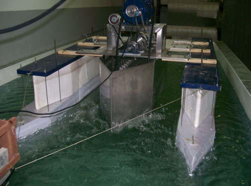 The pressure field is indicated in the figure: 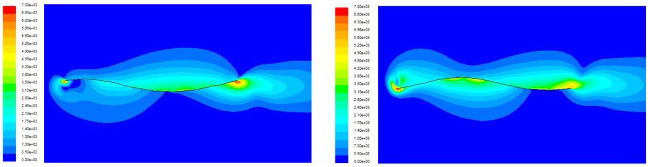 This is a video about the CFD simulation: The main advantage of this system is that it is reversible, i.e., it has the same efficiency either operating forward or backward. This makes it ideal for vehicles that require high maneuverability. COURSES RECOMMENDED: |
| Published 2014-04-04 17:31:42 by Isabel Lamas & J.D. Rodríguez | Open |
| CFD analysis of the marine engine MAN 7S50MC |
The MC series of the two-stroke MAN B&W Diesel were introduced in the early 80s of last century. Its main application is the propulsion of all types of vessels, medium and large sizes. These engines have also been used in terrestrial applications, mainly for production of electrical power. |
| Published 2016-02-12 15:30:35 by Carlos Rodriguez & Isabel Lamas | Open |
| CFD analysis about valve overlap period in the Wartsila 6L 46 four-stroke marine engine |
Wartsila 6L 46 has six cylinders in line, and every cylinder has two inlet and two exhaust valves. The valve follower is of the roller tappet type, where the roller profile is slightly convex for good load distribution. The valve mechanism includes rocker arms working on yokes guided by pins. The Wartsila 46 is provided with Spex (Single pipe exhaust) system and with high efficiency turbocharger. In the field of four-stroke marine engines, the Wartsila 6L 46 has become very popular on new cruise vessels, bulk carriers, cargo vessels, ferries, fishing boats, tankers, etc since it was launched onto the market in 1988. As the Wartsila 6L 46 is a non-reversing engine, in marine applications it is used as auxiliary engine (electric generator) or as main engine connected to a controllable pitch propeller.
Figure 1: Trasversal cut marine diesel engine Wärtsilä 46. Some examples of recent applications are the large Spain tuna
fish vessels “Albatún 2” and “Panama Tuna”. Other example is the chemical
tanker and the cruise vessel "Oasis of the Seas”.
 Figure 2: Engine room in Oasis of the Seas, with Wartsilla 46 as electric generator. Particularly, the valve timing events for the Wartsila
6L 46 are shown in the next Fig. As can be seen, the exhaust valves open 53º
before BDC and close 44º after TDC. On the other hand, the intake valves open
50º before TDC and close 26º after BDC. As can be seen, there is a period of
94º between the exhaust and intake strokes when the intake valves are opening and
the exhaust valves are closing, i.e., all valves are opened simultaneously. This
is called the valve overlap period.  Figure 4: Valves period in Wärtsilä 46. Valve overlap period, and is very important in large four-stroke diesel engines with high turbocharging because the expelling of the burnt gases by the fresh air is more efficient. The overlap period is also useful to refrigerate (the entering air at low temperature refrigerates the walls of the combustion chamber, piston head and exhaust valves. Besides, this air mixes with the burnt gases, which are directed to the turbocharger turbine. If these gases were too hot, the turbine blades would be damaged). For these reasons, the overlap period is very necessary. Unfortunately, the potential for mechanical or gas flow mayhem during the overlap period is obvious. If the cylinder and exhaust pressures are too high, large quantities of exhaust gas can be shuttled into the intake tract. This gas is hot, maybe 1000ºC, and can cause fuel residues on the back of the intake valves. Besides, if exhaust gas occupies the inlet conduct, only a fraction mass of air can be induced into the cylinder. If the air is not enough, the combustion is incomplete and the consequence is that an excess of unburned hydrocarbon emissions are expelled to the atmosphere. Hence, the design process of the engine during the valve overlap period is a very critical issue. In this regard, CFD is a very useful tool. The principle of operation of CFD codes is subdividing the domain into a number of smaller, non-overlapping subdomains. The result is a grid (or mesh) of cells (or elements). In this work, a grid generation program, Gambit 2.4.6, was used to generate the mesh. Due to the movement of the piston and valves, the domain changes into a new position of the calculation and the grid must be automatically reconstruct at each time step. The number of elements varies from 40000 at top dead center, to 500000 at bottom dead center. In order to minimize the number of cells and obtain good convergence, hexahedral elements were used to mesh the cylinder. Unfortunately, hexahedral elements do not adapt properly to the complex geometry of the valves and ducts, for this reason, tetrahedral elements were employed to the cylinder head and ducts. The cylinder head, especially around valves, was refined in order to capture the complex characteristics of the flow. 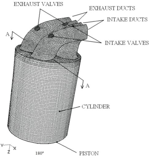 Figure 5: Mesh cylinder Wartsilla 46. At the beginning of the simulation, the pressure descends drastically due to the expansion of the piston. When the exhaust valves are opened, the in-cylinder pressure is slightly superior to the exhaust pressure, therefore burnt gasses are expelled through the exhaust ducts. When the intake valves are also opened, the in-cylinder pressure has an appropriate value, between the exhaust and intake pressures. Consequently, air enters through the intake ducts and burnt gases continue being expelled through the exhaust ducts. The velocity field overlaid with the pressure field. As initial conditions, the velocity inside the cylinder was imposed as the lineal velocity of the piston and it was assumed that the cylinder and exhaust ducts are full of burnt gases (red color), while the intake duct is full of air (blue color). When the exhaust valves are opened, high velocity burnt gases are expelled trough the exhaust ducts. A short time later, the inlet valves are opened and air enters through the intake ducts and burnt gases are expelled through the exhaust ducts. This process of entering fresh air and expelling burnt gases was verified during all the overlap period, i.e., between 310º and 404º. No retrocesión of burnt gases to the intake ducts was produced. This jeans that these operating conditions are adequate. Finally, at the end of the simulation, all valves are closed and residual velocities remain into the cylinder.  Figure 6: Results velocity field with CFD analysis In this work, numerical and experimental tests were performed over a commercial four-stroke marine engine, the Wartsila 6L 46. A CFD model has been used to simulate the exhaust, intake and compression strokes. Special attention was focused on the overlap valve period, which has a crucial influence on the performance of the engine. It was verified that the fluid flow during the overlap period is correct (no reverse flow was obtained). This work was validated, verifying measurements of the in-cylinder pressure. This model is an unprecedented opportunity for engineers to understand the highly complex flow interactions that occur in an engine, providing extra information which can not be analyzed with experimental techniques. Besides, this is a very useful tool do improve the performance of the new designs of engines because it is very easy and reasonably cheap to study the influence of parameters such as the exhaust and intake pressures, engine speed, cam profile design, etc. In order to obtain good results, it is necessary to make several meshes and ensure that the results are independent of the mesh.
COURSES RECOMMENDED: 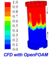 CFD with OpenFOAM online course CFD with OpenFOAM online courseLINKS: Wärtsilä, OpenFOAM, Polish Maritime Research |
| Published 2014-04-09 11:58:46 by Carlos Rodriguez & Isabel Lamas | Open |
| Emissions from Marine Engines and NOx Reduction Methods |
The new IMO Tier III regulation, which appearence in 2016, will further restrict the emission limits in ECAs (Emission Control Areas). In this case they want to establish a 80% reduction of NOx emissions compared with the IMO Tier I regulations in ECAs, whereby the sulfur in these areas will be 0.1% from 2015.
Injection and combustion simulation (temperature range) in a motor MAN D2840LE. Nowadays, diesel engines power more than 90% of the world’s oceangoing ships. Diesel engines have replaced most of the steam turbine systems that were dominant in the 1940s. Most marine fuels are residual heavy fuel oils, which are cheap but contain an important quantity of pollutant substances. Since the 1973 fuel crisis, crude oils have been processed using secondary refining technologies to extract the maximum quantity of refined products (distillates). As a consequence, the concentration of contaminants such as sulfur, ash, asphaltenes, and so on in the residuals has increased. Diesel engines operate with air excess. Fuel is injected at high pressures into air which has been compressed by the moving pistons. This compression raises the temperature of the air sufficiently to cause the fuel to ignite. Combustion proceeds around the periphery of the fuel spray at temperatures around 2000°C. Combustion products have an important percentage of oxygen (O2) and nitrogen (N2). Other emissions from diesel engines are nitrogen oxides (NOx), sulphur oxides (SOx), carbon monoxide (CO), unburnt hydrocarbons (HC), particulates, and so on. Nitrogen oxides are more important in diesel engines than gasoline engines due to the nitrogen and oxygen from the air excess.  Ship emissions may be transported hundreds of kilometers inland. Schwartz (1989) indicated that the median transport velocity of SOx and NOx is about 400 km per day, and the mean residence times of 1 to 3 days, indicating mean transport distances of 400 to 1200 km. Nevertheless, several posterior studies showed that some 70% or more of emissions by international ships occurs within 400 km of land, Corbett et al. (1999); Endresen et al. (2003); Eyring et al. (2005). Oxygen, nitrogen and water vapor are not toxic. Carbon dioxide is not toxic either, but it contributes to the greenhouse effect (global warming). Nevertheless, it is an inevitable product of combustion of all fossil fuels, see reaction (1). Recent studies have estimated that 2.7% of global CO2 emissions are attributable to ships, Eyring et al. (2005), estimating CO2 emissions from shipping of the same order as CO2 emissions from aviation. Speed reduction is an operational measure which offers significant CO2 reductions. A 10% speed reduction gives 20% reduction in fuel consumption over the same distance, Kuiken (2008).  The global and regional impact of air pollution from ship engines has not been addressed until recently, by agencies as Environmental Protection Agency, European Commission and International Maritime Organization. The U.S. Environmental Protection Agency (EPA or sometimos USEPA) is an agency of the United States federal government created for the purpose of protecting human health and the environment by writing and enforcing regulations. The European Commission is the executive body of the European Union responsible for proposing legislation, implementing decisions, upholding the Union’s treaties and day-today running of the EU. In 2002, the European Comisión adopted a European Union strategy to reduce atmospheric emissions from ships. At the international level, the International Maritime Organization (IMO) is an agency which develops and maintains a develop and maintain a comprehensive regulatory framework for shipping and its remit today includes safety, environmental concerns, legal matters, technical co-operation, maritime security and the efficiency of shipping. In 1973, IMO adopted MARPOL 73/78, the International Convention for the Prevention of Pollution From Ships. Marpol 73/78 is one of the most important international marine environmental convections. It was designed to minimize pollution of the seas. Annex VI of the MARPOL convention regulations for the prevention of air pollution by ships, setting limits on sulphur oxide and nitrogen oxides. Concerning SOx, it limits the sulfur content in fuels. Concerning NOx, it establishes a curve which indicates the maximum allowable NOx emission levels related to engine speed, applicable to marine diesel engines built after 2000, 2011 and 2016.
PRIMARY MEASURES:
Decrease of injection duration, delay of start of injection and pre-injection: A delayed injection leads to lower peak pressures and therefore temperatures. Retarding injection timing also decreases the amount of fuel burnt before peak pressure, thus reducing the residence time and degree of after-compression of the first burnt gas. Okada et al. (2001) applied an injection timing retard of 7º to the MAN B&W 4T50MX research engine and they obtained a reduction of NOx by about 30% and an increased in consumption by about 7%. Li et al. (2010) also analyzed the influence of the fuel injection advance angle on nitrogen oxide emissions. Moreno Gutiérrez et al. (2006) studied the consumption and NOx emissions in several marine engines with different injection timings. Al-Sened and Karini (2001) found that pre-injection can be used to shorten the delay period and thus decrease temperature and pressure during the early stages of combustion, resulting in reduced NOx. Besides, they found a decrease in particulares emission. Fankhauser and Heim (2001) also found that pre-injection reduces NOx with a slightly increase in fuel consumption. They studied a Sulzer RT-Flex common rail engine. With triple injection, the fuel charge is injected in separate, short sprays in succession. UIT sequential injection, each of the three nozzles in a cylinder is actuated with different timing. The results showed about 30% NOx reduction with about 8% increase in fuel consumption. Kontoulis et al. (2008) studied numerically the effect of multiple injection strategies in the Sulzer RTA58T marine engine. They demonstrated that, by adding a pilot injection, appropriately timed, it is possible to reduce NOx emissions and save fuel at the same time, particularly 1.7% of fuel reduction. Panagiotis et al. (2009) also studied numerically the multiple injection in a marine engine, the Sulzer RT-flex58T-B and they also got a decrease in NOx and consumption.    Scavenging air cooling: Scavenge air cooling aims to reduce the maximum temperature in the cylinder by lowering the temperature before compression. Holtbecker and Geist (1998) showed that for every 3% reduction, NOx may decrease by about 1% in the Sulzer RTA84C. Sencic (2010) developed a CFD (Computacional Fluid Dynamics) model to simulate the reduction in NOx emissions with reducing the scavenging air temperature. Besides, he studied the exhaust gas recirculation and several injection patterns. He studied the MAN 6S50Mc and Wärtsilä RT-flex50 marine engines.   Water injection: There are three possibilities: fuel-water emulsion, direct water injection or humidification. Introduction of water into the combustion chamber reduces NOx formation due to the increase in the specific heat capacity of the cylinder gases (water has higher specific heat capacity than air) and reduced overall oxygen concentration. The influence of water varies with engine type, but generally 1% percent of water reduces NOx by 1%, Woodyard (2009).  Exhaust gas recirculation (EGR): Exhaust gas recirculation lowers the combustion temperature, and consequently NOx, by reticulating exhaust gases to the charge air. This reduces NOx formation due to the increase in the specific heat capacity of the cylinder gases (water has higher specific heat capacity than air) and reduced overall oxygen concentration. Holtbecker and Geist (1998) found 22% NOx reduction with 6% EGR in the 4RTX54 research engine. However, they postulated that EGR increases smoke, hydrocarbons and CO. Millo et al. (2011) analyzed EGR combined with a Miller cycle in a Wärtsilä W20 marine engine. They obtained NOx reductions up to 90%.    Miller cycle: In four-stroke engines, the Miller cycle uses a higher than normal pressure turbocharge. The inlet valve is closed before the piston reaches bottom dead center on the intake stroke. The charge air then expends inside the engine cylinder as the piston moves towards bottom dead center resulting in a reduced temperature. Schelmmer-Kelling and Rautenstrauch (2001) applied Miller cycle to a Caterpillar engine by earlier closing of inlet valves and slightly increased charge pressure and found that NOx is reduced but smoke is increased.   
SECONDARY MEASURES: The most employed secondary measure in marine
engines is SCR (Selective Catalytic Reduction). SCR involves mixing of ammonia
with the exhaust gas passing over a catalyst. The ammonia is usually supplied
as a solution of urea in water. In order to avoid premature damage of the
catalyst system, it is necessary to employ low sulphur fuels.

Para reducir los óxidos de azufre, existen
unos equipos llamados desulfuradores. Al igual que los SCR, el funcionamiento
se basa en inyectar una sustancia que reaccione químicamente con el gas
contaminante y el compuesto químico formado sea un gas nocivo o un sólido que
precipita en un recipiente habilitado para ello. Esta medida es muy utilizada
ya que es muy complicado y costoso reducir las emisiones de los óxidos de
azufre utilizando medias primarias, al contrario de lo que se hace con los óxidos
de nitrógeno.
 According to MAN B&W (1997) and Wärtsilä (2002), SCR can remove more of 90% of NOx. Jayaran et al. (2011) studied SCR in the MAN B&W 7L32/40 marine engine. NOx emissions for this engine vary from 15 to 21.1 g/kW-h for heavy fuel oil and 8.9 to 19.6 g/kW-h for marine distillate oil. Applying SCR, they reduced the NOx emission factor to less than 2.4 g/kW-h, but it increased the PM emissions by a factor of 1.5–3.8.  
CONCLUSON:
Due to the lean combustion in diesel engines, these have relatively low emissions of carbon monoxide and hydrocarbons. However, nitric oxides and particulate are more important. Due to the efforts to reduce NOx and other pollutants from ships, this paper offers a state of art of the NOx reduction methods. It was shown that there are primary and secondary measures. The well-known drawbacks in employing catalytic converters in ships, mainly the necessity of a reducing agent together with the additional space required for the catalytic reactor, make them barely acceptable to marine diesel engine users. Consequently, primary reduction measures are the first choice for to reduce the formation of pollutants on board ships. EGR and water addition are the most employed primary measures. Both can strongly reduce NOx, but they increment hydrocarbons and CO emissions. Concerning SOx, chemical and washing/scrubbing desulphurization process are complex, bulky and expensive for shipboard applications. The most economical and simplest approach to reduce SOx is thus to use low sulphur fuels.  Currently it is possible to analyze the emissions from engines using CFD (Computational Fluid
Mechanics) and can perform simulations of different injection patterns, humidification load, change of distribution diagrams, Miller cycle, exhaust gas recirculation,
and general any operating
parameter of the engine can be
simulated and tested virtually
by computer, with corresponding savings
of time and money before performing the actual tests and subsequent modifications to the engine.   The utility of modern modeling
tools and simulation software CFD are now indisputable,
allowing to test virtually different models or designs before industrial prototype manufacture, providing this methodology, enormous
advantages and benefits cost savings in prototyping and shortened time in
product development
COURSES RECOMMENDED: CFD with OpenFOAM online course
LINKS:
- Revista Journal Of Maritime Research; Emissions from Marine Engines and Nox Reduction Methods - MAN Diesel & Turbo - HOMEPAGE
- Grupo de Innovaciones Mariñas de la Universidad de La Coruña.
|
| Published 2014-04-11 12:04:42 by Isabel Lamas | Open |
| Entries 1 to 4 of 4 |
 |